
INSTALLATION FOR TWIN MOTOR VIBRATING FEEDERS
TMF Twin Motor Vibrating Feeders can be arranged for either suspension or base installation. Here are helpful considerations for proper installation and maximum feeding efficiency.
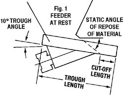
Figure 1
Vibrating Feeder trough
length is determined by the material's static angle of repose and trough slope.
The vibratingfeeder trough must be of sufficient length to assure complete material
shutoff when the feeder is at rest.
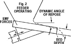
Figure 2
The dynamic angle
of repose is the angle the material seeks while being vibrated and
conveyed.
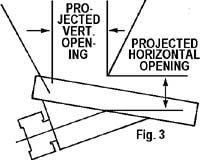
Figure 3
The projected
length and width of the vertical opening should be two to three times greater
than the largest particle dimension. Materials with bridging tendencies require
sufficient openings to assure good product flow. Caution should be exercised in
determining the vertical opening size to avoid excessive bin head-load on the
trough. The projected horizontal opening is determined by the particle size and
bed depth requirements to meet the design feed capacity. The minimum horizontal
opening should be approximately two times the largest particle dimension, but
not less than the bed depth required.
![]()
Best Process Solutions, Inc.
1071 Industrial Parkway North
Brunswick, Ohio 44212
Phone: 330-220-1440 • Fax: 330-220-1447
© 2016. All rights reserved.